DEPRECATED
DEPRECATED
DEPRECATED
This webpage describes the older deprecated version of the Autobed (v1). We recommend building the updated version of the Autobed (v2), which requires fewer materials, less time to build, and does not require directly modifying the Invacare bed components. For the newest version of the Autobed (v2) please go to this page.
DEPRECATED
DEPRECATED
DEPRECATED
We (the Healthcare Robotics Lab at Georgia Tech) have developed a process to modify an Invacare fully electric hospital bed (Model 5410IVC) so that it can be controlled from a web-based interface. We call a bed so modified an ‘Autobed.’ With this feature, users who are unable to operate the standard bed controls, but can access a web browser, are able to position the bed by themselves without having to rely on a caregiver. This page describes how to make this modification to an Invacare bed using relatively cheap, commercially available hardware.
WARNING: THIS WEB PAGE AND ITS ASSOCIATED CONTENTS DESCRIBE PROTOTYPE RESEARCH HARDWARE AND SOFTWARE. USING THESE MATERIALS OR DERIVATIVE MATERIALS COULD ENTAIL RISKS, INCLUDING THE RISK OF SERIOUS BODILY HARM. AS DETAILED IN THE SOFTWARE LICENSE AND HARDWARE LICENSE, WE PROVIDE THIS INFORMATION “AS IS”, WITHOUT WARRANTY OF ANY KIND, EXPRESS OR IMPLIED.
Overview
Total Estimated Price: $125 + Cost of the Invacare Bed and Mattress (~$2000)
Total Estimated Time: ~6 hours
The Autobed system is arranged as follows: The user’s browser sends commands to a Raspberry Pi, which serves the custom web interface. The Raspberry Pi relays these commands to an Arduino microcontroller, which uses digital signals and a custom electronics board to mimic the press of a button on the control pad. These signals are then fed directly into the control box of the Invacare bed where they activate the motors.
The process of modifing the bed is described below in two stages. In the first section, ‘Open Hardware: Building the Autobed’, we modify the Invacare bed’s control box to accept inputs from the Autobed system, and construct the circuitry required to relay inputs from the Arduino board to the bed control board. In the second section, ‘Open Source Software: A Web-Controlled Autobed’, we setup the software for the Autobed system on a Raspberry Pi and an Arduino Uno. Detailed instructions are given for steps, and directly usable code is provided.
NOTE: We have developed and tested this method on the Invacare model 5410IVC bed, and it may or may not work for other models manufactured by Invacare. Do not attempt this modification on hospital beds from other manufactuers. By performing this modification, you will probably void the warrenty on your bed, so proceed with caution.
Skills Required:
- Through-hole Soldering
- Basic tool usage
- Basic Familiarity with the Arduino
- Basic Familiarity with the Raspberry Pi
- Basic Familiarity with the ROS
Raw Materials and Equipment
Here are the places where we purchased the different raw materials and equipment: Keep in mind that you may be able to find these materials for cheaper from other vendors depending on your location. See the alternatives column of the tables below to see if an alternative part can be used.
- Invacare Bed
- Tools Required:
- Soldering iron
- Small diameter solder (less than 0.05”)
- Flat screwdriver
- Phillips screwdriver
- Dremel tool (for making a hole in a plastic casing)
- Needle-nose pliers
- Wire stripper
- Multimeter
- Shear cutter (for clipping wire after soldering to PCB)
- Computer
- Electronics Required:
| Raspberry Pi Accessories | ||||||
|---|---|---|---|---|---|---|
| Description | Vendor | Part # | Quantity | Cost | Total | Alternative |
| Raspberry Pi Model B + 512MB | Element14 | – | 1 | 35$ | 35$ | A computer of your choice that can support ROS |
| 16 GB or higher SD Card and Adapter | Compatible SD Cards | – | 1 | – | – | – |
| SD card reader/writer | Amazon | – | 1 | – | – | May be built in on your computer |
| Wireless USB adapter or ethernet cable | Amazon | – | 1 | – | – | – |
| 6 ft. ethernet cable | Startech | C6PATCH6BK | 1 | $7.99 | $7.99 | any ethernet cable |
| ABS Plastic Box (to house everything) (8.40″ X 5.15″ X 3.15″) | Digikey | 377-1614-ND | 1 | $22.40 | $22.40 | Any box in which holes can be made easily that is at least 8″x 5″x 3″ |
| Arduino Accessories | ||||||
|---|---|---|---|---|---|---|
| Description | Vendor | Part # | Quantity | Cost | Total | Alternative |
| Arduino Uno | Sparkfun | DEV-11021 | 1 | $24.95 | $24.95 | – |
| Arduino Stackable Header Kit | Sparkfun | PRT-10007 | 1 | $1.50 | $1.50 | – |
| 6 in. USB A to B cable | Amazon | – | 1 | $7.16 | $7.16 | Any A to B cable shorter than 2 ft should work |
| Circuit Components | ||||||
|---|---|---|---|---|---|---|
| Description | Vendor | Part # | Quantity | Cost | Total | Alternative |
| PNP amplifying transistors-10 pack | DigiKey | 2N4403-APCT-ND | 1 | $1.70 | $1.70 | Any 6 TO-92 PNP transistors |
| NPN amplifying transistors-10 pack | DigiKey | 2N4401-APCT-ND | 1 | $1.70 | $1.70 | Any 6 TO-92 NPN transistors |
| 1/8 watt 10K ohm resistors – pkg. 50 | DigiKey | CF18JT10K0CT-ND | 1 | $1.78 | $1.78 | Any 10K ohm resistors work |
| 1/8 watt 4.7K ohm resistors – pkg. 50 | DigiKey | CF18JT4K70CT-ND | 1 | $1.78 | $1.78 | Any 4.7K ohm resistors work |
| 1/8 watt 1K ohm resistors – pkg. 50 | DigiKey | CF18JT1K00CT-ND | 1 | $1.78 | $1.78 | Any 1K ohm resistors work |
| 1/8 watt 220 ohm resistors – pkg 50 | DigiKey | CF18JT220RCT-ND | 1 | $1.78 | $1.78 | Any 220 ohm resistors work |
| Solderable prototyping PCB | DigiKey | V2010-ND | 1 | $7.33 | $7.33 | Any solderable prototyping PCB at least 3″x4″ will work |
| 3 ft Serial cable DB9 M/F | Amazon | – | 1 | $8.27 | $8.27 | Any DB9 M/F serial cable at least 3 ft long |
Open Hardware: Building the Autobed
This section describes, in two parts, the the modification of an existing electric bed and assembly of the hardware necessary to relay inputs from the Autobed system to the bed. The first section, ‘Modifying the Invacare Bed’, contains instructions to modify the contrl box of the electric bed. The second section, ‘Building the Autobed Hardware’, contains instructions to build the relay circuit that will allow the Autobed system to send signals to the bed.
Modifying the Invacare Bed
Total Estimated Time ~ 2 hours
- Unplug the Bed from the Wall. Make sure power is disconnected from the bed before proceeding.
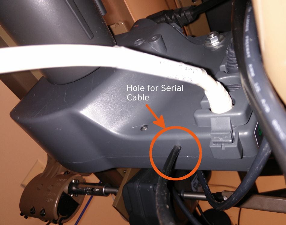
- (Estimated time: 5 mins) Locate the main relay control box on the bed frame (shown circled in the picture below). This is the box that the main AC power cable (from the wall), hand control pad, and all three motors plug into.

- (Estimated time: 5 mins) Disconnect cables from this control box: the AC power cable, the three motors (one plug for each color coded red, yellow, blue), and the bed adjustment controller plug. The AC power cable can be left in place, just make sure the bed is unplugged before proceeding.
- (Estimated time: 5 mins) Remove the control box from the bottom of the bed. If the main relay control box is vertically oriented, it is held in place with a large silver colored bolt and nut. If this is the case, use a pliers to loosen the nut. If the main relay control box is horizontally oriented, it is held in place with a large plastic C-clip. If this is the case use a flat screwdriver to pry off the plastic C-clip.
- (Estimated time: 5 mins) Use the Phillips screwdriver to unscrew the 6 screws holding the relay box together and remove one side of the grey plastic cover. The parts may be lightly stuck together due to sealant along the edge.
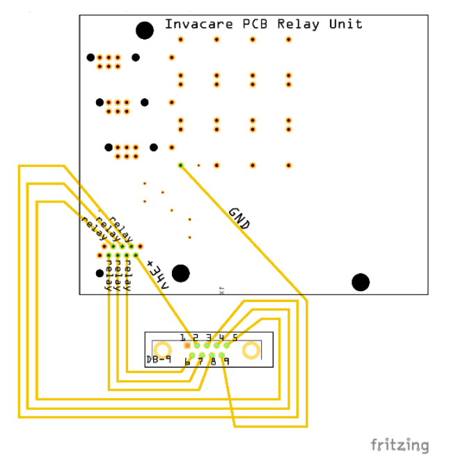
- (Estimated Time: 15 mins) Once it is open you will notice the bottom of the circuit board that looks like the diagram below (Fritzing files for the diagram available here). Cut the DB9 Serial cable approximately 18 inches away from the female end and strip off 4-6 inches of the outer casing. This will reveal the 9 wires that make up this cable. Strip about half an inch of the insulation off of the end of each of these wires.
- (Estimated Time: 10 mins) Using the multimeter (in continuity mode, click here for more info), figure out which pin of the serial cable connects to which wire. It may be useful to label the wires to keep track.
- (Estimated Time: 15 minutes) Use the dremel tool to bore out a hole in the plastic casing of the control box that is big enough to pass the stripped end of the serial cable through. Make the hole on the side of the box as shown in the image below. Pass the end of the cable through this hole and tie a knot in the cable on the inside of the plastic enclosure approximately 7 inches from the stripped end of the cable.
- (Estimated Time: 1 hour) Following the diagram above, solder the serial cable wire connected to pin 2 to +34 volts on the PCB and the wire connected to pin 9 to common ground on the PCB. Solder the wires connected to pins 3-8 to one of the six relays one per relay. Do not use the wire connected to pin 1. While it is okay to mix and match the wires leading to the relays (pins 3-8) because you can reprogram the Arduino microcontroller to command different ones later in the section ‘Setting up the Arduino’, it is critical that the +34 volts and the ground are connected properly.
- (Estimated Time: 5 minutes) Wrap the wires around the side and under the circuit board so the top piece of the large plastic enclosure can fit back on. Reassemble the control box, replacing all 6 screws.
Building the Autobed Hardware
Total Estimated Time ~2 hours
Now that a connector has been wired to the bed’s control circuits, a circuit with switching transistors can be constructed to take the place of the physical buttons on the hand remote. The schematic below shows the circuit diagram for micro-controller command of a single relay (The Fritzing files for this schematic can be downloaded here for better viewing). Using common 34V and ground pins, this single relay control circuit will be replicated 6 times to command all 6 relays.
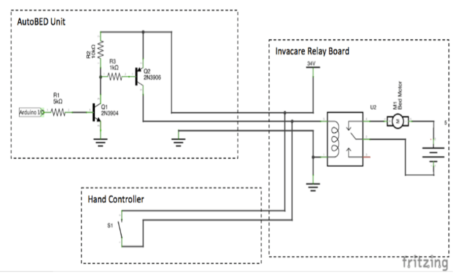
Now you will solder together the transistor circuit that can take a microprocessor signal and turn the switches on. In addition to the schematic above, there is a circuit board diagram and detailed pictures below.
Parts needed:
- 1 solderable PCB from DigiKey (V2010-ND).
- 6 NPN transistors (These are 2N4401-APCT-ND)
- 6 PNP transistors (These are 2N4403-APCT-ND)
- 6 10K ohm resistors, six 5K ohm resistors, six 1K ohm resistors
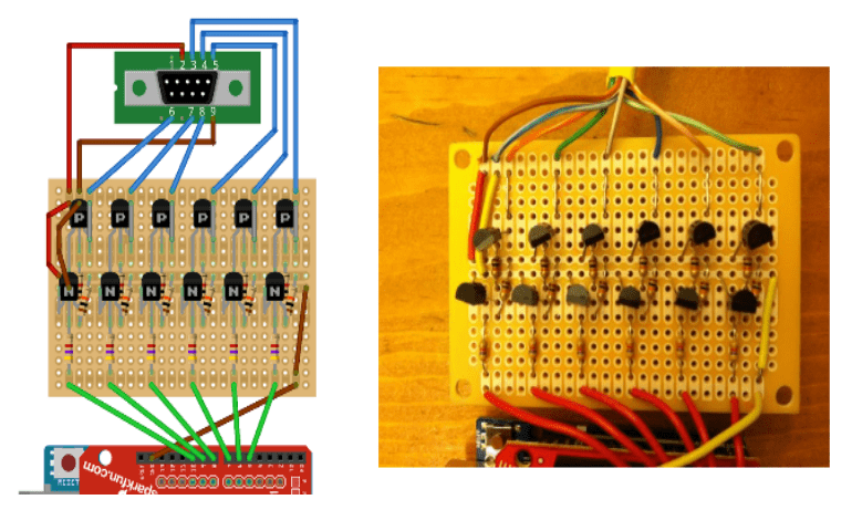
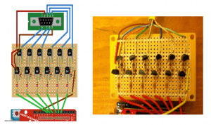
Following the circuit diagram below, first solder the resistors onto the protoboard. Next, solder on the transistors. Make sure the correct transistor and resistor pins are connected to the +34v rail voltage and ground passing horizontally through the center of the board.
- (Estimated time: 15 minutes) On the remaining serial cable (side with the male connector left over from above) strip approximately 4 inches of the outer casing off of the cut end to reveal the 9 wires inside. Strip about half an inch of insulation off the end of each wire.
- (Estimated Time: 10 mins) As previously, using the multimeter (in continuity mode, click here for more info), figure out which pin of the serial cable connects to which wire. It may be useful to label the wires to keep track.
- (Estimated Time: 15 minutes) Use the dremel tool to bore out a hole in the ABS plastic box (or your alternative) that will house the Raspberry Pi, Arduino, and circuit board. The hole should be large enough to pass the stripped end of serial cable through.
- (Estimated Time: 5 minutes) Pass the end of the serial cable through this hole and tie a knot in the cable on the inside of the plastic enclosure approximately 6 inches from the stripped end of the cable to provide strain relief (pulling on the cable from outside the box should pull the knot against the inside of the box, rather than pulling on the connection between the cable and circuit when connected).
- (Estimated Time: 5 mins) Referencing the circuit diagram above, solder the RED wire in the diagram (corresponding to pin 2 on the serial cable and 34+ volts on the Invacare board) to the upper leftmost pin on the protoboard. Then solder the BROWN wire in the diagram (corresponding to pin 9 on the serial cable and common ground on the Invacare board) to the adjacent pin on the protoboard.
- (Estimated Time: 15 mins) Still referencing the diagram above, solder the BLUE wires (corresponding to pins 3-8) to their corresponding places on protoboard, according to the diagram. Note that in the picture on the right, some of the colors are incorrect — follow the left diagram for wire coloring and use the picture on the right as a reference for soldering components on the protoboard.
- (Estimated time: 15 mins) Connect small bare jumper wires on the protoboard leading from each of the BLUE wires to the respective collector of each PNP transistor. Use the picture above on the right to visualize the orientation of these jumpers.
- (Estimated time: 10 mins) Connect RED and BROWN jumper wires from just below two uppermost pins where RED and BROWN wires on the serial cable were soldered to the +34V rail and ground rail passing horizontally along the protoboard. The upper rail (in the image) is for +34v and the bottom rail is for ground. NOTE: At this point, set your multimeter to the “Continuity Tester” mode. Check whether the entire 34v and GND rails are connected throughout the circuit. This is a common source of problems. Also, make sure that the +34v and GND rails are not shorted together at any point. In other words, make sure that the RED and BROWN wires are not connected to each other. A short can seriously damage components and possibly the bed controller itself, so check twice before moving on.
- (Estimated time: 15 mins) Connect GREEN wires leading out of the bottom pin row on the protoboard and solder them adjacent to the 4.7k-Ohm resistors. Similarly to the BLUE wires, the pictures on the right above show incorrect wires coloring, so follow the left diagram.
- (Estimated time: 5 mins) Connect the GREEN wires that are already soldered to the protoboard into digital I/O pins 2 through 7 on the Arduino. Then connect a BROWN ground wire leading from the Arduino to the protoboard. However, before you do this, please see the instructions in the ‘Setting up the Arduino’ section first.
- (Estimated time: 20 mins) Mount the circuit board into the ABS plastic enclosure. You may want to use a dremel tool to bore out necessary holes for the other wires such as the power cable for the Raspberry Pi. However, do not screw the lid onto the enclosure yet because the Arduino and Raspberry Pi still must be configured in the software section.
Open Source Software: A Web Controlled Autobed
Our open source software includes code to send signals to the Autobed hardware (constructed in the previous section) with a web interface in order to control your Invacare electric bed. We assume some familiarity with ROS, but full instructions on setting up your own Raspberry Pi with ROS are located below.
Setting up the Raspberry Pi
If you wish to use a Raspberry Pi to run the Autobed software, please use the following setup instructions. Otherwise, proceed to the section “Setting up the Arduino”.
Setup
Installing the Operating System (Raspian)
- We use the Raspian OS for the Raspberry Pi. The image file can be downloaded here.
- Use the instructions located here to write the image file to an SD card.
- Plug the wireless USB adapter into one of the USB ports of the Raspberry Pi.
- Place the microSD card into the slot on the back of your Raspberry Pi and plug it in to power(see theRaspberry Pi documentation for help with this step). The red power light should come on and the activity lights beside it should start to flash as the Raspberry Pi boots. If the green light does not flash, you have not written the image file to the SD card correctly. If you are having trouble writing the Raspian image file to your SD card see this link for additional help.
- Once your Raspberry Pi has booted, connect it to the internet through either an ethernet or wireless connection. Use these instructions to connect the Raspberry Pi to your wireless network.
Installing ROS
The Autobed software runs on ROS Fuerte. See these instructions for installing ROS Fuerte on your Raspberry Pi. Note that only the ROS-Base install is required, NOT ROS-Full or Desktop Installations.
Installing Pillow
Pillow (the Python Imaging Library) is required to run the Autobed software. Download and installation instructions can be found here. More information about Pillow can be found here.
Installing the Autobed Software
The following instructions will walk you through installing the Autobed-specific software onto your Raspberry Pi.
- Dependencies: To run the Autobed software you will need to install the following ROS packages, using ROS Fuerte versions of each, if applicable:
- Get all the code from the Autobed Git Repository and unzip it to get the latest version of the code.
- Make (cd into directory, then type
rosmake) the following ros packages:autobed_engineautobed_web
- Finding the IP Address of the Raspberry Pi: In order to get the right URL for the Autobed web interface, you will need to know the IP address of your Raspberry Pi. To find the IP address use either the
ifconfigcommand on the Raspberry Pi, use these instructions, or check the list of clients connected on your router’s web interface. - Setting a static IP Address for the Raspberry Pi: If your Raspberry Pi disconnects from your router, it will often receive a new IP address when it reconnects, which will change the URL for the Autobed controls. It is therefore preferable to assign it a static IP address, which can be done following the instructions here.
Setting up the Arduino
The following instructions will help you set up your Arduino UNO to communicate with your Raspberry Pi and Autobed Hardware.
- Retrieve the code: Download the file ‘hrl_arduino.ino’ from our GitHub repository here.
- To upload this Arduino code to your Arduino UNO you will need the Arduino IDE, which can be downloaded and installed folling the instructions here.
- Upload the Arduino sketch to the Arduino UNO:
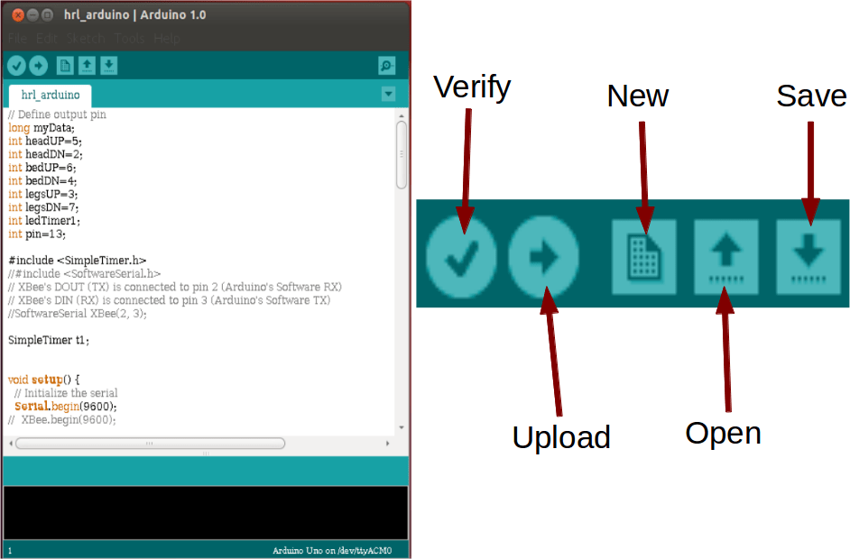
- Open the Arduino IDE.
- Open the file ‘hrl_arduino.ino’ in the IDE. It should look like this:
- Connect your Arduino UNO to your computer with the USB cable.
- In the development environment, go to ‘Tools’ then ‘Serial Port’ and select your Arduino board.
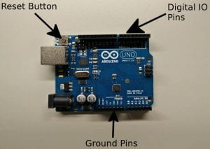
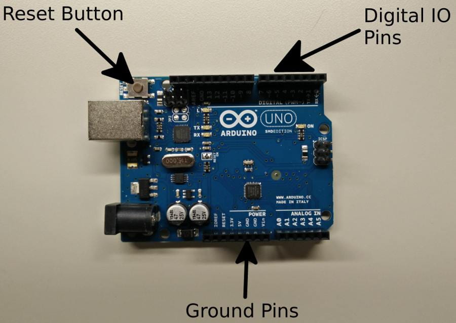
- Find and press (and release) the reset button on your Arduino UNO (see picture below). Depending on the specific version it should be a small silver button either on the middle right side of the board or on the upper left-hand corner or the board.
- In the Arduino IDE press ‘Upload’ (the button with an arrow pointing to the right).
- Make sure that the sketch compiles and uploads successfully. The IDE should show success, or any errors, at the bottom of the window. The TX/RX lights on the Arduino UNO should flash during the upload.
- After the program has finished uploading disconnect the Arduino board from your computer.See this page for help with the Arduino development environment or this page for help uploading a program to your Arduino board.
- Connect the Arduino to the Autobed Circuit
- On the circuit board, find the 6 wires that are each connected to a 4.7k resistor (The GREEN wires in the diagram below).
- Find the digital I/O pins on the Arduino board located along the top edge (see picture above).
- From left to right, connect these wires to digital pins 2-7 on the Arduino board respectively.
- Connect the BROWN wire in the diagram above to either of the ground pins marked ‘GND’ on the bottom edge of the Arduino board (see picture above).
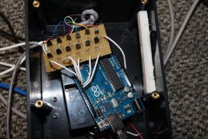
- Using the 6 inch USB cable, connect the Arduino to the USB port on the Raspberry Pi.After these steps, it should look like this:
 Here’s a close up view of the digital I/O pins on the Arduino:
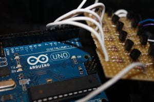
- On the circuit board, find the 6 wires that are each connected to a 4.7k resistor (The GREEN wires in the diagram below).


- On the Raspberry Pi, navigate to
hrl_autobed_dev/autobed_weband run the command:/bin/bash ./scripts/autobed_start.sh. This should start the Autobed’s web server, and make the web interface available on the local network. - Go to the following URL on your local network, and control your robotic bed:http://<IP_ADDRESS_OF_RASPBERRY_PI>:8888/autobed_web/autobed.html
For example: http://192.168.0.104:8888/autobed_web/autobed.html would be the URL if the Raspberry Pi had the IP address 192.168.0.104. Note: If controlling the bed wirelessly, you must be connected to the same wireless network as the computer running the Autobed software. - Depending on the wiring, it is likely that the commands from the web interface will not control the correct function on the bed. To fix this:
- In your favorite text editor, on the Raspberry Pi, open
hrl_autobed_engine/src/autobed_engine.pi. - Find the line (toward the top of the file):
CMDS = {'headUP': 'A',

'headDN': 'F',

'bedUP':'C',

'bedDN':'D',

'legsUP':'B',

'legsDN':'E'}
This tells the python script which command to send to the Arduino based on the command from the web interface. - While running the web interface, make note of which command buttons produce which effects.
- Determine from this list which letter commands produce which effects.
- Modify the
CMDSvariable inautobed_engine.pyso that the proper letters match the correct commands. For example, the new arrangement might be:
CMDS = {'headUP': 'F',

'headDN': 'A',

'bedUP':'B',

'bedDN':'C',

'legsUP':'E',

'legsDN':'D'}
- In your favorite text editor, on the Raspberry Pi, open
- Once this is done, and you have verified that the Autobed is working expected, place the Autobed controller box in a place where it doesn’t interfere with the motion of the bed.
Useful Links
Support
This research is funded by the Department of Education (National Institute on Disability and Rehabilitation Research, H133E130037).
License
This work requires the user to download and modify Raspbian OS. Raspbian is distributed for free under the GNU General Public License v2.
The software for this project is licensed under The MIT License.
 “Autobed v2: A Web-Controlled Robotic Bed” Hardware by Healthcare Robotics Laboratory is licensed under a Creative Commons Attribution 4.0 International License.
The Team
The main contributors to the development of this hardware were Phillip Grice, Yash Chitalia, Megan Rich, Henry Clever, Henry and Jane Evans and Prof. Charles C. Kemp. Henry Clever and Phillip Grice were the lead students for the first versions of the hardware for the Autobed and also initiated this documentation process.Yash Chitalia and Megan Rich were the main student developers of the embedded version of the first verison of the Autobed. Phillip Grice was the lead student developer for the second version of the Autobed described in this page (Autobed 2.0). We would like to thank Henry Evans and Jane Evans for their support throughout the continuous testing of the Autobed.
 |
 |
 |
 |
| Phillip Grice Ph.D. Student |
Yash Chitalia Ph.D. Student |
Megan Rich Undergraduate Student |
Henry Clever Ph.D. Student at NYU |
 |
|
||
| Henry and Jane Evans Research Collaborators |
Charles C. Kemp, Ph.D. Director |
||